")
")
")
")
")
")
")


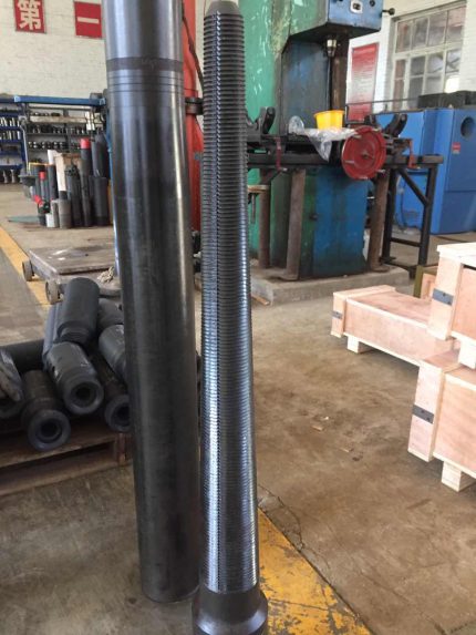
Oil Drill BOP Control System Bottles for Accumulator Wellhead BOP Control Unit
$6,000.00
Accumulator unit for BOP stacks is a very important equipment which controls BOP stacks and gate valves controlled by hydraulic pressure especially in drilling and workover operations. It is necessary to accurately operate and maintain the hydraulic control system. It consists of remote control system, driller’s panel, air cable (except electrical type), pipe rack (electrical warming system available for cold area), high pressure manifold, protection room, etc.
Specifications:
Electrical type BOP accumulator unit
|
Model |
Number of controlled objects |
Accumulator unit |
Explosion–proof motor Power (Kw) |
Pump system displacement |
Rated operating pressure of the system (Mpa) |
Maximum operating pressure of the system (Mpa) |
|||
|
Total volume (L) |
Available liquid volume (L) |
Installation mode |
Triplex pump (mL/r) |
Pneumatic pump |
|||||
|
FKDQ1920-13 |
13 |
80×24 |
960 |
Side / Rear |
18.5×3 |
80×3 |
120×5 |
21 |
31.5 |
|
FKDQ1600-14 |
14 |
80×20 |
800 |
Side / Rear |
18.5×2 |
80×2 |
120×4 |
21 |
31.5 |
|
FKDQ1600-12 |
12 |
80×20 |
800 |
Side / Rear |
18.5×2 |
80×2 |
120×4 |
21 |
31.5 |
|
FKDQ1600-10 |
10 |
80×20 |
800 |
Side / Rear |
18.5×2 |
80×2 |
120×4 |
21 |
31.5 |
|
FKDQ1440-14 |
14 |
60×24 |
720 |
Side / Rear |
18.5×2 |
80×2 |
120×4 |
21 |
31.5 |
|
FKDQ1280-10 |
10 |
80×16 |
640 |
Side / Rear |
18.5×2 |
80×2 |
120×3 |
21 |
31.5 |
|
FKDQ1280-9 |
9 |
80×16 |
640 |
Side / Rear |
18.5×2 |
80×2 |
120×3 |
21 |
31.5 |
|
FKDQ1280-8 |
8 |
80×16 |
640 |
Side / Rear |
18.5×2 |
80×2 |
120×2 |
21 |
31.5 |
|
FKDQ1280-7 |
7 |
80×16 |
640 |
Side / Rear |
18.5×2 |
80×2 |
120×2 |
21 |
31.5 |
|
FKDQ1200-17 |
17 |
60×20 |
600 |
Side / Rear |
18.5×2 |
80×2 |
120×3 |
21 |
31.5 |
|
FKDQ1200-9 |
9 |
60×20 |
600 |
Side / Rear |
18.5×2 |
80×2 |
120×3 |
21 |
31.5 |
|
FKDQ1200-8 |
8 |
60×20 |
600 |
Side / Rear |
18.5×2 |
80×2 |
120×2 |
21 |
31.5 |
|
FKDQ960-8 |
8 |
60×16 |
480 |
Side / Rear |
18.5×2 |
80×2 |
120×2 |
21 |
31.5 |
|
FKDQ960-7 |
7 |
60×16 |
480 |
Side / Rear |
18.5×2 |
80×2 |
120×2 |
21 |
31.5 |
|
FKDQ800-8 |
8 |
40×20 |
400 |
Side / Rear |
18.5 |
80 |
120 |
21 |
31.5 |
|
FKDQ 800-7 |
7 |
40×20 |
400 |
Side / Rear |
18.5 |
80 |
120 |
21 |
31.5 |
|
FKDQ 800-6 |
6 |
40×20 |
400 |
Side / Rear |
18.5 |
80 |
120 |
21 |
31.5 |
|
FKDQ720-7 |
7 |
60×12 |
360 |
Side / Rear |
18.5 |
80 |
120 |
21 |
31.5 |
|
FKDQ 720-6 |
6 |
60×12 |
360 |
Side / Rear |
18.5 |
80 |
120 |
21 |
31.5 |
|
FKDQ 640-6 |
6 |
40×16 |
320 |
Side / Rear |
18.5 |
80 |
120 |
21 |
31.5 |
|
FKDQ 640-5 |
5 |
40×16 |
320 |
Side / Rear |
18.5 |
80 |
120 |
21 |
31.5 |
|
FKDQ 480-5 |
5 |
40×12 |
240 |
Side / Rear |
18.5 |
80 |
120 |
21 |
31.5 |
|
FKDQ 480-4 |
4 |
40×12 |
240 |
Side / Rear |
18.5 |
80 |
120 |
21 |
31.5 |
|
FKDQ320-5 |
5 |
40×8 |
160 |
Side / Rear |
15 |
60 |
120 |
21 |
31.5 |
|
FKDQ320-4 |
4 |
40×8 |
160 |
Side / Rear |
15 |
60 |
120 |
21 |
31.5 |
|
FKDQ320-3 |
3 |
40×8 |
160 |
Side / Rear |
15 |
60 |
120 |
21 |
31.5 |
|
FKDQ240-3 |
3 |
40×6 |
120 |
Side / Rear |
15 |
60 |
120 |
21 |
31.5 |
|
FKDQ200-4 |
4 |
25×8 |
100 |
Side / Rear |
15 |
60 |
120 |
21 |
31.5 |
|
FKDQ160-3 |
3 |
40×4 |
80 |
Side / Rear |
15 |
60 |
120 |
21 |
31.5 |
|
FKDQ150-2 |
2 |
50×3 |
75 |
Side / Rear |
15 |
60 |
120 |
21 |
31.5 |
|
FKDQ125-3 |
3 |
25×5 |
62.5 |
Side / Rear |
7.5/11 |
28 |
× |
21 |
21 |
|
FKDQ80-3 |
3 |
40×2 |
40 |
Side / Rear |
7.5 |
28 |
× |
21 |
21 |
|
FKDQ80-2 |
2 |
40×2 |
40 |
Side / Rear |
7.5 |
28 |
× |
21 |
21 |
|
FKDQ75-2 |
2 |
25×3 |
62.5 |
Side / Rear |
7.5 |
28 |
× |
21 |
21 |
|
FKDQ63-2 |
2 |
63×1 |
31.5 |
Side / Rear |
7.5 |
28 |
× |
21 |
21 |
|
FKDQ50-2 |
2 |
25×2 |
25 |
Side / Rear |
7.5 |
28 |
× |
21 |
21 |
|
FKDQ40-2 |
2 |
40×1 |
20 |
Side / Rear |
7.5 |
28 |
× |
21 |
21 |
|
FKDQ25-2 |
2 |
25×2 |
12.5 |
Side / Rear |
7.5 |
28 |
× |
21 |
21 |
|
FKDQ25-1 |
1 |
25×2 |
12.5 |
Side / Rear |
7.5 |
28 |
× |
21 |
21 |
Pneumatic type BOP accumulator unit
|
Model |
Number of controlled objects |
Accumulator unit |
Explosion–proof motor Power (Kw) |
Pump system displacement |
Rated operating pressure of the system (Mpa) |
Maximum operating pressure of the system (Mpa) |
|||
|
Total volume (L) |
Available liquid volume (L) |
Installation mode |
Triplex pump (mL/r) |
Pneumatic pump |
|||||
|
FKQ1920-7 |
7 |
80×24 |
960 |
Side / Rear |
18.5×3 |
80×3 |
120×6 |
21 |
31.5 |
|
FKQ1600-14 |
14 |
80×20 |
800 |
Side / Rear |
18.5×2 |
80×2 |
120×4 |
21 |
31.5 |
|
FKQ1600-12 |
12 |
80×20 |
800 |
Side / Rear |
18.5×2 |
80×2 |
120×4 |
21 |
31.5 |
|
FKQ1600-10 |
10 |
80×20 |
800 |
Side / Rear |
18.5×2 |
80×2 |
120×4 |
21 |
31.5 |
|
FKQ1600-10 |
10 |
80×20 |
800 |
Side / Rear |
18.5×4 |
80×4 |
120×12 |
21 |
31.5 |
|
FKQ1440-14 |
14 |
60×24 |
720 |
Side / Rear |
18.5×2 |
80×2 |
120×4 |
21 |
31.5 |
|
FKQ1280-10 |
10 |
80×16 |
640 |
Side / Rear |
18.5×2 |
80×2 |
120×3 |
21 |
31.5 |
|
FKQ1280-9 |
9 |
80×16 |
640 |
Side / Rear |
18.5×2 |
80×2 |
120×3 |
21 |
31.5 |
|
FKQ1280-8 |
8 |
80×16 |
640 |
Side / Rear |
18.5×2 |
80×2 |
120×2 |
21 |
31.5 |
|
FKQ1280-7 |
7 |
80×16 |
640 |
Side / Rear |
18.5×2 |
80×2 |
120×2 |
21 |
31.5 |
|
FKQ1200-9 |
9 |
60×20 |
600 |
Side / Rear |
18.5×2 |
80×2 |
120×3 |
21 |
31.5 |
|
FKQ1200-8 |
8 |
60×20 |
600 |
Side / Rear |
18.5×2 |
80×2 |
120×2 |
21 |
31.5 |
|
FKQ960-8 |
8 |
60×16 |
480 |
Side / Rear |
18.5×2 |
80×2 |
120×2 |
21 |
31.5 |
|
FKQ960-7 |
7 |
60×16 |
480 |
Side / Rear |
18.5×2 |
80×2 |
120×2 |
21 |
31.5 |
|
FKQ800-8 |
8 |
40×20 |
400 |
Side / Rear |
18.5 |
80 |
120 |
21 |
31.5 |
|
FKQ 800-7 |
7 |
40×20 |
400 |
Side / Rear |
18.5 |
80 |
120 |
21 |
31.5 |
|
FKQ 800-6 |
6 |
40×20 |
400 |
Side / Rear |
18.5 |
80 |
120 |
21 |
31.5 |
|
FKQ720-7 |
7 |
60×12 |
360 |
Side / Rear |
18.5 |
80 |
120 |
21 |
31.5 |
|
FKQ 720-6 |
6 |
60×12 |
360 |
Side / Rear |
18.5 |
80 |
120 |
21 |
31.5 |
|
FKQ 640-6 |
6 |
40×16 |
320 |
Side / Rear |
18.5 |
80 |
120 |
21 |
31.5 |
|
FKQ 640-5 |
5 |
40×16 |
320 |
Side / Rear |
18.5 |
80 |
120 |
21 |
31.5 |
|
FKQ 480-5 |
5 |
40×12 |
240 |
Side / Rear |
18.5 |
80 |
120 |
21 |
31.5 |
|
FKQ 480-4 |
4 |
40×12 |
240 |
Side / Rear |
18.5 |
80 |
120 |
21 |
31.5 |
|
FKQ320-5 |
5 |
40×8 |
160 |
Side / Rear |
15 |
60 |
120 |
21 |
31.5 |
|
FKQ320-4 |
4 |
40×8 |
160 |
Side / Rear |
15 |
60 |
120 |
21 |
31.5 |
|
FKQ320-3 |
3 |
40×8 |
160 |
Side / Rear |
15 |
60 |
120 |
21 |
31.5 |
|
FKQ240-3 |
3 |
40×6 |
120 |
Side / Rear |
15 |
60 |
120 |
21 |
31.5 |
|
FKQ200-4 |
4 |
25×8 |
100 |
Side / Rear |
15 |
60 |
120 |
21 |
31.5 |
|
FKQ160-3 |
3 |
40×4 |
80 |
Side / Rear |
15 |
60 |
120 |
21 |
31.5 |
|
FKQ150-2 |
2 |
50×3 |
75 |
Side / Rear |
15 |
60 |
120 |
21 |
31.5 |
|
FK125-3 |
3 |
25×5 |
62.5 |
Side / Rear |
7.5/11 |
28 |
× |
21 |
21 |
|
FK80-3 |
3 |
40×2 |
40 |
Side / Rear |
7.5 |
28 |
× |
21 |
21 |
|
FK80-2 |
2 |
40×2 |
40 |
Side / Rear |
7.5 |
28 |
× |
21 |
21 |
|
FK75-2 |
2 |
25×3 |
62.5 |
Side / Rear |
7.5 |
28 |
× |
21 |
21 |
|
FK63-2 |
2 |
63×1 |
31.5 |
Side / Rear |
7.5 |
28 |
× |
21 |
21 |
|
FK50-2 |
2 |
25×2 |
25 |
Side / Rear |
7.5 |
28 |
× |
21 |
21 |
|
FK40-2 |
2 |
40×1 |
20 |
Side / Rear |
7.5 |
28 |
× |
21 |
21 |
|
FK25-2 |
2 |
25×2 |
12.5 |
Side / Rear |
7.5 |
28 |
× |
21 |
21 |
|
FK25-1 |
1 |
25×2 |
12.5 |
Side / Rear |
7.5 |
28 |
× |
21 |
21 |


General Inquiries
There are no inquiries yet.
Related products
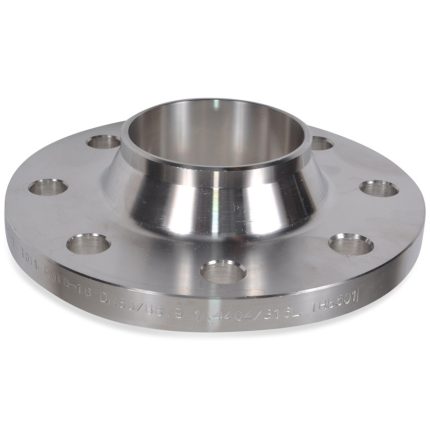

ANSI 4130 10000PSI Weld Neck Flange

API 6A Weld Neck Flanges are pipe flanges attach by welding the pipes to the neck of the flanges. This transfers stress from the flange to the pipe instead. It also reduces the stress concentration from the base of the hub. Welding neck flanges remove stress concentration and allow full working pressure and they are often used for high pressure applications. The inside diameter of the flange is designed to match the pipe's inside diameter. Weld neck pipe flanges are typically provided with a raised face, flat face, or RTJ facing.
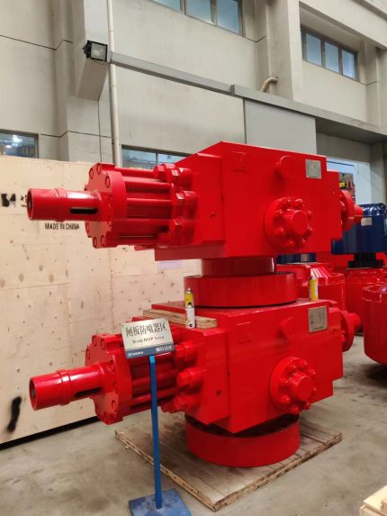
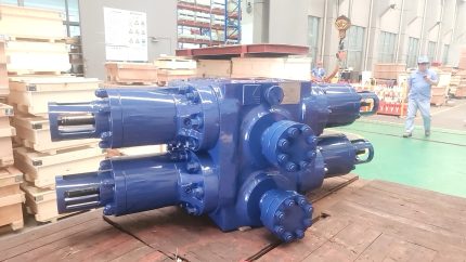
API 16A Double Ram Bop/Blowout Preventer
Ram type BOPs are field proven products that are designed for a variety of operations from workovers to high pressure, critical service operations for land drilling and subsea service. It consists of the BOP body, bonnet, hydraulic cylinder assembly, operating piston, ram change cylinder, ram opening/closing piston, locking screw, ram assembly, sealing parts etc. Top, bottom and outlet connection dimensions conform to Specification for Drilling through Equipment API Spec 16A.
Made up of the high-strength and high-tenacity alloy steel, the pressure-bearing parts (like BOP body, bonnet etc.) are formed through external refining and proper heat treatment, preventing the harmful chemical components and nonmetallic inclusion strictly from materials and ensuring BOP to be safe and reliable. The body ram chamber adopts the long runway to reduce stress concentration. Both the bonnet switch and ram switch are driven by the hydraulic pressure and adopts the same one oil line. The bonnet employs the same one oil line and operation to open and close the ram. Moreover, the bonnet employs the same one oil line and operation to close and open the ram.
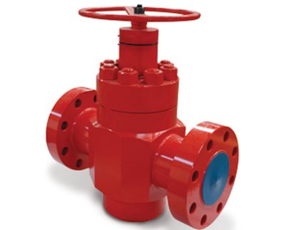
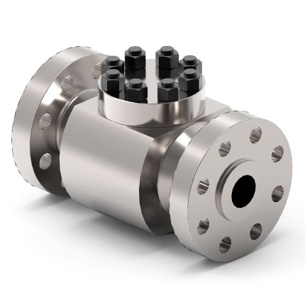
API 6A 3000- 7500 PSI wellhead equipment Mud Gate Valves for oil
FC valve
1. Full-bore design, effectively eliminate the pressure drop and eddy current, slow flow of solid particles in the valve.
2. The unique sealing, make the switch torque greatly reduced
3. Between bonnet & body and gate & seat are adopt metal to metal seal
4. Between gate and seat are adopt metal to metal seal, Surface spraying (heap) welding hard alloy , has good abrasion resistance, corrosion resistance.
5. Seat ring is fixed with plate, keep well steady
6. Stem has back seal structure so as to replace seal ring of stem with pressure
7. There is seal grease injection valve on bonnet side so as to repair seal grease , and provided seal and lubricate performance of gate and seat
8. It is match with all kind of pneumatic (hydraulic) actuator as customer's requirements
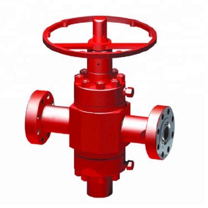
Expanding gate valve
1. Gate is fission expanding structure
2. Realizing low torque or low wear during switch
3. Between bonnet and body are adopt metal to metal seal
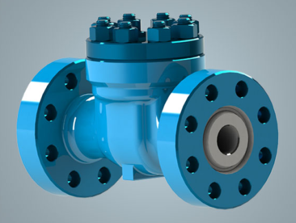
API hign quality High Pressure Flanged End Swing Check Valve for oilfield
API 6A Check Valve, also referred to non-return valve, or one-way valve, is a valve that normally allows fluid (liquid or gas) to flow through it in only one direction. An important concept in check valves is the cracking pressure which is the minimum upstream pressure at which the valve will operate. We can produce both swing type check valve and lift type check valve. Available in bore sizes from 1-13/16" to 7-1/16" and pressure ratings from 2,000 to 15,000 PSI. The standard material is forged AISI4130 alloy. All of our Check Valves are fully designed, manufactured, and tested as per API 6A and API 16C standards and have been widely used on oilfield wellhead Christmas tree and manifolds with reliable performance.
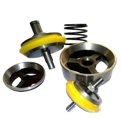
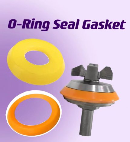
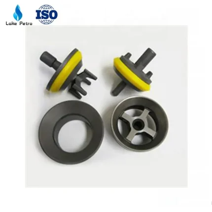
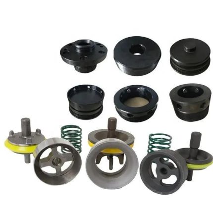
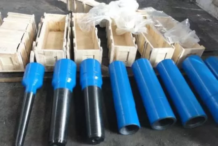
API Standard Mud Pump Valve Assembly for Mud Pump Parts
Mud Pump Parts Valve assembly/Valve body/Valve seat
1.The valve body and valve seat of valve assembly are made from high-quality knot steel treated with 20CrMnTi carburizing and
quenching processes.
2.The surface hardness is greater than HRC 60.
3.The conical surface is ground finished to ensure a high requirement for roughness and geometric dimension.
4.The rubber sheet is made of polyurethane material which improves the service life of valve assembly, the operational use time is more than 300 hours.

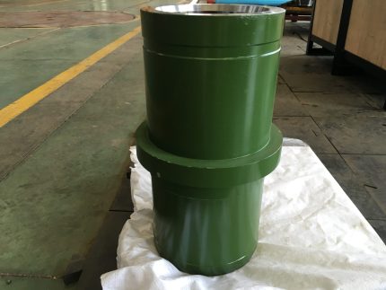
Mud Pump Spare Parts – Bimetallic/Ceramic Liner
Mud pump spare parts as one of the expendables what need to be replaced frequently in drilling service, the quick matching, high quality and competitive price will be ensured from Lake Petro. Our products are 100% interchangeable with the original equipment manufacturer in every way. The parts name and model will be detailed in the following sections.
